1 Integrity – a global challenge
Based on enhanced electromagnetic induction:

ε—— induced electromotive force of the receiving coil;
S ——total area of the receiving coil;
Φ——magnetic flux;
B——magnetic field strength
When the thickness of the steel pipe (oil/casing) changes or there are defects, the induced electromotive force ε will change. Through analysis and calculation, damage to the tubular structure can be determined under single- and double-layer pipe columns.
2 Data acquisition principle

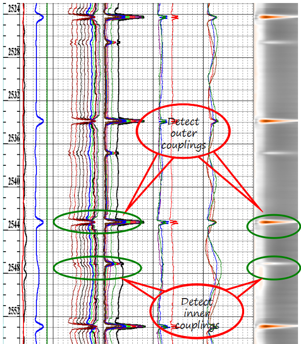
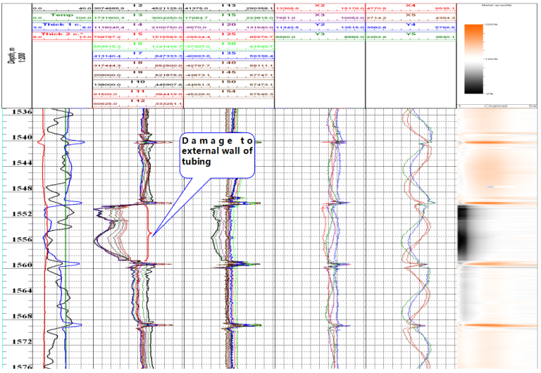
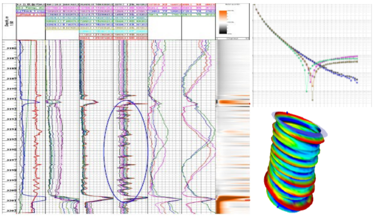
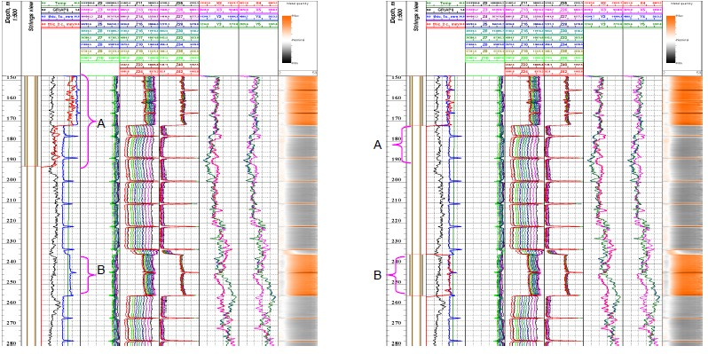
Longitudinal and transverse probes achieve full coverage inspection of pipe columns: Longitudinal probe: large detection range, full coverage; Transverse probe: symmetrical detection (deformation); increases the weight of damaged parts within the detection range; can identify smaller damage (holes); Ground system performs discrete sampling at equal time intervals of 2.5ms; The sampled data is transmitted directly to the ground system for storage; Patent analysis software analyzes and simulates the detection data; Enhanced interpretation platform, zooms in and analyzes individual detection points to improve interpretation accuracy. |
3 Main technical indicators of the instrument

Composition (from top to bottom): Enhanced electronic module and gamma probe, longitudinal probe, transverse probe, temperature sensor。

4 Case study
Run history
- Over 600 LeakPoint operations globally
- Over 1100 leaks successfully located
- Operating efficiency > 90%
Client list

Case 1
Diagnosis
- leak rate s 2.30 liters/min
- 58 leaks confirmed in one run
- All leaks at casing connections
- >16 hours for operation
Value
- Reduced NPT vs conventional technologies
- Information enabled optimal choice of remedial action
- Procedures changed for construction of subseguent wells


Case 2
Well Y56 in Malaysia, 2.5″ thickened tubing+ 7″ casing

Case 3
Canadian KBXX well, with a 2-7/8″ nickel alloy tubing (wall thickness of 5.5mm) and a 7″ casing (wall thickness of 12.65mm) (H2S content of 7%)

The outer casing string (7′ casing) was seriously distorted and the outer wall of the casing was damaged.
Case 4
Canadian XX well (H2S content 12%), where the outer casing has slipped off.

The above figure shows that the first layer of the wellbore casing is a 9-5/8″ casing with a steel grade of SM95S and a wall thickness of 11.99mm. The second layer of the wellbore casing is a 13-3/8″ casing with a casing shoe located at 192.18m. The steel grade and wall thickness of the second layer casing are unknown, and a wall thickness of 12mm is used for calculation.